
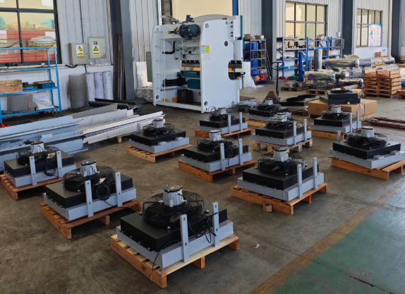
Retrofitting a drilling rig is rarely as simple as removing an old component and installing a new one. Even when the replacement equipment has a similar appearance, differences in mounting positions, pipe connections and available space can turn a straightforward job into a larger engineering task.
Oil cooling equipment is a good example. On many drilling rigs, the cooler must fit among structural supports, hydraulic lines, electrical assemblies and other components. There may be little freedom to change its position, particularly on machines that have already undergone several modifications.
When a rig is being refurbished or adapted for a different application, the oil cooling arrangement deserves attention early in the planning process. The cooler needs to meet the required thermal duty, but it also has to work within the machine's existing layout.
This article looks at the practical side of drilling rig oil cooler integration, from measuring the installation space to checking hose routing, mechanical support and commissioning requirements.
Why Oil Cooler Retrofits Require More Than a Matching Replacement
Drilling equipment often remains in service through multiple maintenance cycles. During that time, individual components may be repaired, replaced or modified. The cooling arrangement that originally came with the machine may no longer match the surrounding layout exactly.
For example, replacement piping may follow a slightly different route from the original installation. Additional guards or electrical equipment may occupy space that was previously available. A modified fan arrangement may also change the airflow path through the cooling compartment.
These details matter when installing a new cooler.
A Drilling Rig Lubricating Oil Cooler can be considered during equipment refurbishment when a suitable replacement or revised cooling arrangement is required. However, the component must be evaluated against the actual machine rather than selected only from photographs or external dimensions.
The first question is whether the work involves a direct replacement or a genuine modification.
With a direct replacement, the intention is to restore the original configuration using a technically equivalent component. The existing connections, mounting arrangement and operating requirements provide the starting point.
A retrofit may involve more substantial changes. The cooler location might need to move, the mounting structure may require revision, or the available airflow could be different from the original design.
In this situation, an engineering review is necessary to determine whether the proposed configuration remains appropriate.
Another consideration is the purpose of the oil circuit. Drilling machinery can contain both lubrication and hydraulic systems. Although both may use oil coolers, their flow conditions, pressure requirements and operating functions can differ.
The circuit must be identified before choosing a component.
A cooler intended for a lubrication system should not automatically be treated as interchangeable with a hydraulic oil cooler simply because the two units have similar dimensions.
For refurbishment projects, it is useful to document the original arrangement before removing the old equipment. Photographs of the installed cooler, connection locations and surrounding components can preserve information that may otherwise be lost during disassembly.
This is particularly valuable when original drawings are unavailable or the machine has been modified over time.
How Installation Space and Mounting Design Affect Cooler Selection
One of the main challenges in drilling rig retrofits is the limited space available for additional equipment.
Oil coolers may be mounted near engine compartments, structural frames, access panels or other mechanical assemblies. The installation position can influence both service access and the way cooling air moves around the component.
Before choosing a replacement, the available space should be measured with the surrounding equipment in place.
Measuring the available installation envelope
Overall cooler dimensions are only the beginning.
The installation survey should also identify the space required for fluid connections, mounting brackets, nearby hoses and maintenance access.
A cooler may fit within the measured opening but still be difficult to install because a connection points toward a structural member or a hose cannot be routed without excessive bending.
The position of surrounding components should therefore be recorded along with the cooler dimensions.
Where possible, measurements should be taken from fixed reference points on the machine. This helps reduce ambiguity when the information is transferred to a manufacturer or engineering team.
Mounting support and equipment vibration
Drilling rigs experience mechanical vibration during operation. The cooler and its mounting assembly must be suitable for the loads expected in the installation.
The weight of the cooler is only one consideration. Support location, bracket stiffness, connection flexibility and the behavior of the surrounding structure can also affect mechanical loading.
Improper mounting may place unintended stress on connections or other parts of the cooler assembly.
For a retrofit, the existing supports should be inspected before they are reused. Corrosion, deformation, fatigue damage or previous repairs may affect their suitability.
The following table highlights important installation checks.
| Installation item | What to verify | Why it matters |
|---|---|---|
| Overall dimensions | Height, width and depth | Confirms the physical installation envelope |
| Mounting points | Hole positions, support arrangement and bracket condition | Supports secure installation |
| Connection clearance | Space around oil inlet and outlet ports | Allows practical hose or pipe routing |
| Airflow clearance | Available inlet and discharge paths | Helps prevent airflow restriction |
| Service access | Space for inspection, cleaning and removal | Supports future maintenance |
| Nearby equipment | Guards, wiring, piping and structural components | Identifies possible interference |
| Vibration exposure | Expected operating environment and support requirements | Supports mechanical compatibility |
A compact aluminum plate-fin design may be useful where installation space is restricted. However, the core dimensions, mounting arrangement and thermal performance must still be reviewed together.
The smallest cooler is not necessarily the most suitable one.
What Should Be Checked When Connecting the Oil Circuit?
Oil circuit integration requires careful attention because the cooler becomes part of an existing fluid system.
Connection size and location are obvious concerns, but the internal flow requirements and pressure limitations are equally important.
Before installation, the engineering team should establish the normal operating flow, expected pressure conditions and allowable pressure drop through the cooler.
These values help determine whether the proposed component is suitable for the circuit.
Hose routing and connection orientation
Flexible hoses are common in many types of mobile and industrial equipment, but they still require appropriate routing and support.
A hose should not be forced into position simply because the new cooler connection differs from the original arrangement.
Excessive bending, twisting, abrasion against nearby components and insufficient clearance can create maintenance or reliability problems.
Routing should follow the applicable hose manufacturer's requirements, including minimum bend radius, pressure rating, temperature compatibility and support arrangements.
If rigid piping is used, the connection geometry and support requirements become particularly important.
A retrofit should avoid introducing unnecessary mechanical loads into the cooler ports.
Pressure drop and flow compatibility
Any heat exchanger introduces some resistance to fluid flow.
The pressure drop depends on the oil properties, flow rate and internal passage arrangement. A replacement with different internal geometry may produce a different pressure loss even if its external dimensions are similar.
The complete lubrication circuit must remain within the equipment manufacturer's requirements.
Where the original cooler specification is available, it should be used as a reference. If the circuit has been modified, current operating data may be required.
It is also important to consider oil viscosity at the relevant temperatures. Flow behavior during cold startup can differ from conditions after the machine reaches its normal operating temperature.
The proposed cooler should therefore be assessed against the intended operating range rather than a single nominal condition.
Keeping the circuit clean during installation
Contamination control is an important part of cooler replacement.
When hoses and connections are opened, dust, metal particles or other foreign material can enter the circuit unless suitable precautions are taken.
Open ports should be protected using clean, appropriate covers or caps. Installation tools and surrounding work areas should be kept clean, and replacement components should be inspected according to the applicable maintenance procedure.
The cleanliness requirements of the oil circuit should be established before the work begins.
Once installation is complete, filling, venting and commissioning must follow the machine and component manufacturer's instructions.
A technically suitable cooler can still experience problems if the surrounding oil circuit is contaminated or incorrectly assembled.
Why Airflow Planning Matters During Equipment Modification
The physical installation of a cooler is only one part of a successful retrofit. For an air-cooled design, the surrounding airflow arrangement has a direct influence on heat rejection.
An aluminum plate-fin oil cooler typically relies on airflow across its external heat transfer surfaces. The internal passages carry the working fluid, while the external airflow removes heat.
The actual cooling result depends on the temperature and quantity of air passing through the core.
A retrofit that changes the equipment enclosure, fan location or ventilation openings can affect this airflow.
Air inlet and discharge arrangements
Cooling air needs a clear path through the heat exchanger.
If the inlet is partially blocked by another component, the amount of air passing through the core may be reduced. If hot discharge air recirculates toward the inlet, the incoming air temperature may increase.
Both conditions can affect cooling performance.
The installation layout should therefore be reviewed before finalizing the cooler position.
Where a fan is included, its performance must be considered together with the resistance of the installed airflow path. A fan's nominal airflow rating does not necessarily represent the airflow delivered through a complete equipment enclosure.
Why fan direction and spacing matter
The relationship between the fan and cooler influences airflow distribution.
A fan positioned too close to surrounding obstructions may not operate under the conditions assumed in its performance data. Uneven airflow across the heat exchanger can also affect the use of the available cooling surface.
The appropriate arrangement depends on the specific fan, core and enclosure design.
Rather than applying a universal spacing rule, the installation should be evaluated using the relevant equipment specifications.
Cooling airflow in dusty working environments
Drilling machinery often operates where airborne dust and debris are present.
The position of the cooler can influence how much contamination reaches its surfaces and how easily it can be inspected.
An installation that requires extensive disassembly before the fins can be cleaned may create unnecessary maintenance difficulties.
Where possible, the layout should provide practical access to exposed cooling surfaces without compromising machine safety or mechanical protection.
Airflow planning should therefore consider both initial thermal performance and the conditions expected during continued operation.
How Should a Retrofitted Oil Cooler Be Commissioned?
Once the mechanical installation is complete, the cooler should be checked as part of the complete oil circuit before normal operation resumes.
Commissioning is not simply a matter of starting the machine and confirming that the cooler becomes warm.
The installation needs to be reviewed for mechanical security, fluid integrity and operating compatibility.
Mechanical and fluid connection checks
Before startup, confirm that the cooler is mounted according to the approved installation requirements.
Connections should be checked for correct assembly and appropriate support. Hoses and pipes should have sufficient clearance from moving parts, sharp edges and sources of excessive heat.
Any pressure testing, leak testing or other acceptance checks should follow the applicable equipment procedures and approved technical requirements.
The system must be handled safely because oil circuits can contain hot fluid and stored pressure.
Checking operating conditions
After the machine has been prepared for operation, the commissioning procedure should include relevant temperature and pressure measurements.
The oil inlet and outlet temperatures can provide useful information when considered together with flow rate, machine load and ambient conditions.
A temperature difference across the cooler does not independently establish whether the heat exchanger is performing correctly.
The result should be compared with the expected duty and the equipment manufacturer's operating requirements.
Where suitable measurement points are available, pressure drop may also be reviewed.
If the cooler introduces an unexpected restriction, the cause should be investigated before the machine is returned to its intended duty.
The following checklist can support commissioning planning.
| Commissioning stage | Inspection or measurement | Acceptance basis |
|---|---|---|
| Mechanical installation | Mounting, brackets and clearance | Approved drawings and installation instructions |
| Fluid connections | Hose routing, fittings and sealing | Circuit and component requirements |
| System cleanliness | Contamination control and preparation | Relevant maintenance procedures |
| Initial operation | Leaks, abnormal vibration and visible issues | Approved startup checks |
| Thermal evaluation | Oil temperatures and operating load | Required operating conditions |
| Hydraulic evaluation | Flow and pressure drop where applicable | Specified circuit limits |
| Final documentation | Results and approved changes | Project acceptance requirements |
Recording the completed modification
A retrofit should be documented after commissioning.
The records may include the final cooler model, approved drawings, connection details, relevant operating measurements and any changes made to the original machine layout.
These documents are useful during future maintenance and component replacement.
Without them, maintenance personnel may assume the machine still uses its original cooling configuration.
A clear record helps the next service team understand what was changed and which technical requirements were used for approval.
Long Term Serviceability Should Be Part of the Retrofit Plan
A cooler retrofit should not be judged only by whether the equipment operates successfully immediately after installation.
The design also needs to remain practical throughout the machine's service life.
Maintenance access is one important consideration. The cooler should be positioned so that routine inspection and approved cleaning procedures can be performed without unnecessary disruption.
The arrangement of hoses, supports and nearby components can determine how difficult future maintenance becomes.
Another consideration is replacement accessibility.
If the cooler eventually needs to be removed, the surrounding layout should allow safe disconnection and handling. A tightly integrated assembly may save installation space but create additional work when maintenance is required.
The availability of technical documentation also matters.
Dimensioned drawings, connection specifications and component identification help maintenance teams obtain suitable replacements without repeating the original measurement process.
For drilling rigs that operate under demanding conditions, service planning should account for contamination, vibration and changes in the working environment.
A cooler that meets its initial thermal requirements but is difficult to inspect may not be the most practical solution for the application.
A retrofit should solve the installation problem without creating another one
The purpose of modifying a drilling rig cooling arrangement is to achieve mechanical and thermal compatibility with the existing equipment.
That requires attention to more than the heat exchanger itself.
Mounting structure, oil flow, connection geometry, airflow and maintenance access must be reviewed as parts of the same system.
Where a standard replacement meets the required conditions, extensive modification may not be necessary. Where the original arrangement no longer fits the application, a customized solution can be evaluated against the machine's documented requirements.
The final decision should be based on engineering compatibility rather than external appearance alone.
For equipment refurbishment projects, a carefully planned oil cooler retrofit can help preserve the intended operation of the lubrication system while making future maintenance easier to manage.
The strongest approach is to begin with accurate measurements, confirm the operating requirements and evaluate the complete installation before approving the revised cooling arrangement.





Reviews
There are no reviews yet.